Difference between core type and case type transformer
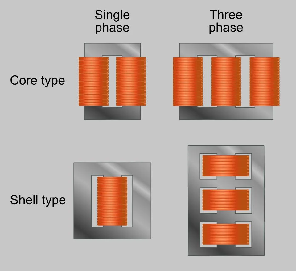
The main difference between transformer core and shell transformers are core transformers with two pins and two yokes, and case transformers with three pins and two yokes. Core transformers are used for high voltages. While a shell-type transformer is used for low voltage.
A transformer is a static device that increases or decreases voltage as required. Power transmission and distribution would not be possible without the use of transformers. As such, transformers are the backbone of an electrical network.
Transformers can be classified into two categories.
Core Type Transformers
Shell Type Transformers
In this article, we will first understand core and case-type transformers and the key differences between them. Now let’s talk about the basics of core and case-type transformers.
What is a Core Type Transformer?

The magnetic core of a transformer has foils cut from L-shaped strips. The transformer has two horizontal parts called the yoke and two vertical parts called the legs. The coil is placed on the limb. 50% of the primary and secondary windings are placed on each pin of the core. Therefore, interlocking the primary and secondary windings reduces the leakage flux.
In a core transformer, the low-voltage coil is placed close to the core, and the high-voltage coil is applied around the low-voltage coil. With this arrangement, the insulation requirement greatly reduces the cost of the transformer.
The transformer core can be easily disassembled for repair and maintenance. In addition, the transformer core has better natural cooling capacity. However, core transformers draw large magnetizing currents compared to shell transformers.
Core transformers are widely used in high-voltage applications such as power and distribution transformers.
What is a clamshell transformer?
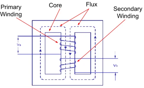
Case transformers have two outer pins and one center pin.
In a shell transformer, the primary and secondary windings are located at the center pin, the outer pin having no windings. The outer branch completes the path of the magnetic circuit. Thus, the central branch carries the entire flow and the lateral branches carry half the flow. This is why a central limb is twice as large as the outer limb.
In a shell transformer, the low and high-voltage windings are alternately placed on the center pin. The coil is called a sandwich coil or a disc coil due to the position of the coil in a sandwich style.
The transformer housing provides better resistance to electromagnetic forces generated between current-carrying conductors. In addition, the transformer draws very little magnetizing current due to the shorter magnetic path. However, the major disadvantage of the shell transformer is its poor natural cooling. and thus they are suitable for low-voltage applications such as low-power circuits and electronic circuits.
Difference Between Core and Shell Transformer
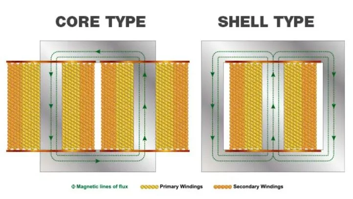
The following table highlights the key differences between core and shell transformers.
| Basis of Difference | Core Transformer | Shell Transformer |
| Definition | Mesh cross-section | Magnetic circuits have one branch in the middle and two on the outside. The primary and secondary windings placed on the central branch are called shell transformers. |
| Wrap-around type | Coil around core | The magnetic core surrounds the coil |
| Shape of grating | U and I plate | U and T plate or E and I plate. |
| three branches and two yokes. | Soul cross section can be square, rectangular decimal with two or three steps. | Rectangular core cross-section. |
| Heating | Since the transformer handles a large amount of energy, the heat output is also greater. | In instrument transformers, much less heat is generated. |
| Cooling requirement | Heat generated in transformer is higher. Therefore, they require additional cooling devices. | The temperature rise of the measurement transformer is not critical. As such, natural cooling is sufficient. |
| Storage tank | Storage tank is an important part of power transformer. | Measurement transformer without reserve tank. |
| Load limiting factor | In the case of power transformers, temperature rise is the main factor to limit the load. | In instrument transformers, accuracy is the main limiting factor of the load. |
| Design Considerations | For power transformers, cost, efficiency and voltage regulation are the main design considerations. | Accuracy and cost are the main design considerations for instrument transformers. |
| Cost | Transformer cost is very high. | Instrument transformers are much cheaper than power transformers. |
| Number of limbs and yoke | No. of two limbs and two yoke. | No. of two limbs and two yokes. |
| Number of magnetic circuits | Single magnetic circuits. | Two magnetic circuits. |
| Winding type | concentric winding (or cylindrical winding). | sandwich winding (or alternating winding or disc winding). |
| Coil placement | The coils are located on two separate branches. | The primary and secondary windings are located on the center pin. |
| Conductive materials | Other conductive materials for coils. | Less wound conductor material. |
| Iron to build core | Out-of-sequence is current crosses the clearance and connects to the container. The circulating current causes the tank to heat up. | Add iron to build cores. |
| Core loss | The total flux going through the entire core, the larger the core loss. | Half of the total flux flows through the entire core, so losses in the core are less. |
| Copper loss | No more copper loss. | Low copper loss |
| Natural cooling | Good natural cooling | Poor natural cooling |
| Repair and maintenance | Easy repair and maintenance because the transformer is detachable easily. | It is difficult to dismantle the transformer. |
| Average coil length | Shorter average coil length. | The average coil length is longer. |
| Average core length | In core transformers, the average length of the magnetic core is longer. | In shell transformers, the average length of the magnetic core is shorter. |
| % Impedance | Lower percent impedance | Higher percent impedance |
| Container overheating | Out-of-sequence current crosses the clearance and connects to the container. The circulating current causes the tank to heat up. | The tank heater in a case-type transformer is no problem because it provides a path for zero-sequence current. |
| Application | High voltage and high power | The magnetic circuit of a core transformer has two vertical parts called legs and two horizontal parts called yokes. The windings placed on the branches are called core transformers. |

